MicroFlow & MicroFlow-i
MicroFlow & Microflow-i are a non-contacting liquid flow velocity sensor that uses microwave technology to transmit short pulses that reflect off a moving surface back to the sensor and are analysed to determine the velocity.
They are extremely low power consumption makes it the ideal velocity solution for sewerage network monitoring (CSO) and all remote installations where mains power is unavailable.
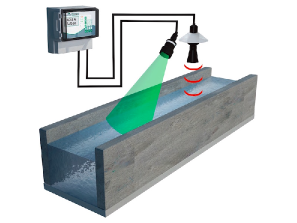
Designed for open channel flow applications where the channel has no existing primary measurement device (e.g. weir or flume). Can be combined with a Pulsar level transducer and controller in order to provide a complete flow measurement system.
GITEKI Mark acquired(MicroFlow & MicroFlow-I, both)
Description
- Microwave Flow Sensor
- Accuracy: The greater of ±1.5% or 0.05m/s (Microflow-i) / The greater of ±0.5% or 0.05m/s (MicroFlow)
- Communication: HART compatible, 4-20mA loop powered (Microflow-i) / RS485 and Modbus RTU (MicroFlow)
Specification
Catalog PDF|
MicroFlow & MicroFlow-i |
|
| Model |
MicroFlow-i MicroFlow |
|
PHYSICAL |
|
| Sensor body dimensions: |
Diameter 90mm x height 140mm |
| Sensor body weight: |
Nominal 1kg |
| Sensor body material: |
Valox 357 |
| Mounting connection: |
Via 1” BSP back mounted thread or 20mm via supplied adaptor |
| Mounting angle: |
45° optimum and mounted at the centre line of the channel with a clear uninterrupted view |
| Transducer cable extensions: |
2-core screened 5-core screened |
| Maximum separation: |
Up to 1000m Up to 500m |
|
ENVIRONMENTAL |
|
| Enclosure protection: |
IP68 |
| Max. and min. temperature (electronics): |
-20°C to +60°C |
|
APRROVALS |
|
| CE & radar approvals: |
Listed in the Certificate of Conformity within the manual |
| ATEX approval: |
Ex II 1 G D, Ex ia IIC T4 Ga, Ex ia IIIC T135°C Da (Directive 2014/34/EU) Ex II 2 G D, Ex mb IIC T4 Gb, Ex mb IIIC T135°C Db, Ta= -20°C to +60°C |
|
PERFORMANCE |
|
| Accuracy: |
The greater of ±1.5% or 0.05m/s The greater of ±0.5% or 0.05m/s |
| Velocity range: |
0.2 - 6m/s |
| Operational range: |
Up to 3m height |
| Optimum installation: |
Install at an angle of 45° in line with the flow. More information is provided within the manual – see the ‘Locating the MicroFlow sensor’ section |
| Max. channel width per sensor: |
1.5m |
| Radar: |
K-Band (ISM) |
| Transmitter power: |
<15 dBm |
| Beam width: |
20° inclusive |
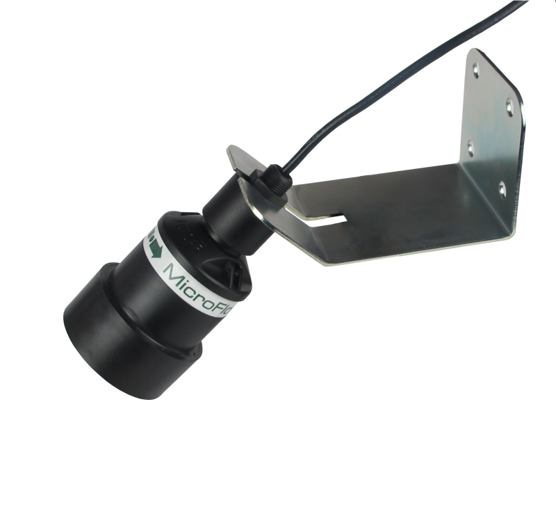
MicroFlow installed on bracket
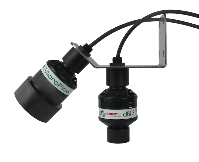
Installation example: MicroFlow-i and dBi3 on bracket